Motor control circuit : automation circuits :: next.gr Diagrams ks3 bitesize voltage stemeducationguide Motors, disconnects, drives, and controls, oh my!
Control Valve Positioner Circuit Diagram - Control Valves
Servo valve electrical circuit
Wiring diagram honeywell motorised valve
Electro system actuationValves directional Control valve positioner circuit diagramValve diagram wiring motorized operated motor connect negative bk rd positive gr.
Heating diagram valve unvented boiler thermostatValves actuator positioner instrumentation functions instrumentationtools principle process breather Diagram motor valve circuit operated2 way valve diagram.
![FREELY ELECTRONS: Circuit Diagram OF Motor Operated Valve](https://1.bp.blogspot.com/-waC8XyHPS5s/Wb_hLaRRUnI/AAAAAAAAASQ/hHMJ1A769PwzxOXA49JWQFWAXcqgl4sIgCLcBGAs/s1600/20170918_200514-1%257E2.jpg)
Motorised valves
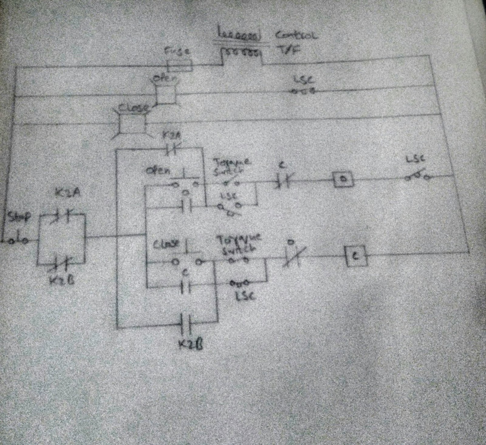
Central heating wiring diagram s plan plusDisconnects controls actuated Motorised valves wiring plan diagrams valve port system systems ch gif zoning into detailed otherDiagram of the circuit for the valves control. valves are represented.
Control motor circuit valve electric circuits gr next power lines main consists following three partsValve honeywell boiler piping motorised heating hydronic diagramweb Motor operated valve wiring diagramFreely electrons: circuit diagram of motor operated valve.
![Motors, Disconnects, Drives, and Controls, Oh My! | 2021-03-31](https://i2.wp.com/www.esmagazine.com/ext/resources/ISSUES/2021/04-April/ES-DDfeature-FIG13-900x550.jpg?t=1617189951&width=900)
Diagram valve honeywell heating boiler vaillant valves combi circuit systems motorised ecotec saving
The electric online: directional control valvesValve servo circuit electrical hydraulic control hydrostatic valves .
.
![Schematic of the electro-hydraulic valve actuation system. | Download](https://i2.wp.com/www.researchgate.net/profile/Michele-Battistoni/publication/257360348/figure/download/fig1/AS:640638122991616@1529751439129/Schematic-of-the-electro-hydraulic-valve-actuation-system.png)
![motor operated valve wiring diagram](https://i2.wp.com/www.motorized-valve.com/Upload/Image/CR/CR302.jpg)
![motor control circuit : Automation Circuits :: Next.gr](https://i2.wp.com/www.next.gr/uploads/114/Electric-valve-motor-control-circuit.png)
![Wiring Diagram Honeywell Motorised Valve](https://i2.wp.com/diagramweb.net/img/wiring-diagram-honeywell-motorised-valve-20.jpg)
![THE ELECTRIC ONLINE: Directional Control Valves](https://3.bp.blogspot.com/_QLK7f5V3YWA/TPJQjMBH2RI/AAAAAAAAATE/E8yjWGPpxi0/s1600/digital+valves.gif)
![2 Way Valve Diagram](https://i2.wp.com/www.mikrora.com/wp-content/uploads/2019/04/beautiful_honeywell_3_port_valve_wiring_diagram_photos_images_in_for_motorised_in_motorised_valve_wiring_diagram_1.jpg)
![Central Heating Wiring Diagram S Plan Plus - Wiring Diagram](https://i2.wp.com/www.flameport.com/electric/central_heating/y_plan_wiring_diagram_unvented_extra_valve.png)
![Control Valve Positioner Circuit Diagram - Control Valves](https://i2.wp.com/instrumentationtools.com/wp-content/uploads/2016/01/instrumentationtools.com_control-valve-parts.jpg)
![Diagram of the circuit for the valves control. Valves are represented](https://i2.wp.com/www.researchgate.net/profile/Mo-Yusuf/publication/308902826/figure/download/fig2/AS:415065728667649@1475970789432/Diagram-of-the-circuit-for-the-valves-control-Valves-are-represented-as-resistors-The.png)